Author: After Market Commercial Solutions

Forklift Planned Maintenance for Busy Warehouses: Daily Checks, Service Intervals and Breakdown Prevention

Forklift Planned Maintenance

In a busy warehouse, forklifts are not just machines. They are part of the workflow. They move stock, feed production lines, load trucks, unload deliveries and keep operations moving between departments. When a forklift breaks down, the delay can spread across the entire site. Picking slows down. Dispatch falls behind. Operators wait. Other forklifts are pushed harder. That is why forklift planned maintenance is not only a workshop task. It is an operational strategy.

For South African warehouses, logistics hubs, retail distribution centres and industrial sites, the pressure on material handling equipment can be intense. Heat, dust, long shifts, uneven surfaces and tight turnaround times all increase wear. A planned maintenance programme helps prevent breakdowns before they disrupt the business.

Why Reactive Forklift Repairs Cost More Than Planned Maintenance

Reactive repairs usually happen at the worst time. A forklift fails during a shift, stock needs to move, and the site needs a fast repair. The visible cost is the repair invoice. The hidden cost is often much higher.

Unplanned forklift downtime can cause:

  • delayed loading and dispatch
  • reduced picking speed
  • missed delivery windows
  • overtime costs
  • increased pressure on remaining forklifts
  • safety risks from rushed workarounds
  • higher emergency repair costs
  • premature wear on other machines

Planned maintenance changes the approach. Instead of waiting for something to fail, the forklift is inspected, serviced and corrected before the issue becomes a stoppage.

Daily Operator Checks That Prevent Bigger Workshop Repairs

Operators are the first line of defence. They use the forklift every day, so they are often the first to feel changes in performance. A simple daily check can catch faults before they become expensive.

Daily Pre-Start Checklist

Before using a forklift, operators should check:

  • tyres for chunking, cracking or abnormal wear
  • forks for visible cracks, bends or heel wear
  • fork locking pins
  • mast chains for damage or uneven tension
  • hydraulic hoses for leaks
  • fluid leaks under the machine
  • battery condition and charge level
  • warning lights on the dash
  • horn, lights and reverse alarm
  • seatbelt condition
  • brakes and steering response
  • lifting and tilting operation

These checks do not need to be complicated, but they must be consistent. A checklist that is actually completed every day is more valuable than a detailed form that no one uses.

Weekly Inspection Points for Supervisors

Daily checks are helpful, but weekly checks should be slightly more detailed. Supervisors or workshop staff should look for patterns that operators may miss.

Weekly inspections can include:

  • brake performance check
  • steering play check
  • tyre wear comparison
  • battery terminals and charger plug condition
  • mast roller condition
  • chain lubrication and stretch signs
  • hydraulic fluid level
  • coolant level on applicable units
  • air filter condition in dusty environments
  • unusual noises during operation

Weekly checks also help identify repeated operator complaints. If three different operators report slow lifting on the same forklift, that is a maintenance warning, not a preference issue.

Forklift Service Intervals: Why One Schedule Does Not Fit Every Fleet

Forklift service intervals should be based on usage, environment and operating hours. A forklift working one short shift in a clean warehouse will not need the same service intensity as a forklift working long shifts in a dusty yard.

Factors that affect service intervals include:

  • operating hours per week
  • load weight and frequency
  • indoor vs outdoor use
  • dust and debris levels
  • floor condition
  • number of operators per unit
  • battery or fuel type
  • temperature and ventilation
  • availability requirements

A well-managed fleet uses hour meter readings, service history and fault trends to build the right schedule.

Battery and Charging Care

Battery problems are one of the most common causes of forklift disruption. Whether the unit is lead-acid, lithium or another electric configuration, charging routines directly affect availability.

Good Battery Practices

  • charge using the correct charger
  • keep charging areas clean and ventilated
  • inspect plugs and cables for damage
  • avoid pulling chargers by the cable
  • follow correct opportunity charging rules
  • monitor abnormal heat during charging
  • report reduced runtime early
  • keep battery records per forklift

For lead-acid batteries, watering and cleaning routines are also important. For lithium units, charger compatibility and disciplined charging schedules protect performance.

Hydraulic Leak Checks

Forklift hydraulics control lifting, tilting and load handling. A hydraulic issue can quickly become a safety risk.

Operators and technicians should look for:

  • wet hose ends
  • oil marks on cylinders
  • slow lifting
  • jerky mast movement
  • whining hydraulic pump noise
  • dropping load height
  • fluid around the undercarriage

Small leaks should never be ignored. Hydraulic leaks can introduce contamination, reduce system pressure and create slip hazards on the floor.

Tyres, Brakes and Steering Inspections

Forklifts operate close to people, stock, racking and vehicles. Tyres, brakes and steering are therefore safety-critical.

Tyres

Worn or damaged tyres can affect:

  • stability
  • braking
  • steering
  • vibration
  • operator comfort
  • load control

Brakes

Brake warning signs include:

  • weak stopping
  • grinding noises
  • pulling to one side
  • excessive pedal travel
  • burning smell
  • poor parking brake hold

Steering

Steering issues may show as:

  • excessive steering wheel play
  • knocking noises
  • uneven tyre wear
  • poor turning response
  • hydraulic leaks around steering components

These areas should be checked often, especially in sites with tight turning, ramps, loading bays and frequent stop-start movement.

Warning Signs Operators Should Report Immediately

Operators should never wait for a scheduled service if they notice:

  • dashboard warning lights
  • unusual hydraulic noise
  • burnt smell
  • poor braking
  • steering looseness
  • visible leaks
  • slow lifting
  • forks not sitting level
  • battery overheating
  • charger faults
  • vibration while travelling
  • sudden loss of power

A quick report can prevent a breakdown, protect the operator and avoid damage to goods or racking.

Breakdown Prevention Through Reporting

A planned maintenance programme works best when reporting is simple. If reporting is too complicated, faults are ignored until they become breakdowns.

A good forklift reporting system should include:

  • forklift ID or fleet number
  • operator name
  • date and shift
  • description of issue
  • photos where helpful
  • severity level
  • action taken
  • technician notes

Over time, this creates a useful fault history. Managers can see which units have repeat problems, which operators need training, and which parts should be stocked.

Maintenance Planning for Multi-Shift Warehouses

Multi-shift warehouses need extra planning because downtime windows are limited. Maintenance should be scheduled around operation patterns, not forced into peak activity.

Useful strategies include:

  • rotating forklifts out for service
  • planning minor checks between shifts
  • scheduling major services during lower-volume periods
  • keeping critical wear parts available
  • grouping similar units for efficient servicing
  • maintaining a backup unit if possible

The objective is not only to service forklifts. It is to service them without disrupting the flow of the warehouse.

AMCS Planned Maintenance Support

AMCS supports material handling equipment with practical maintenance, servicing and repair solutions. For forklift fleets, planned maintenance can help improve reliability, extend machine lifespan and reduce avoidable breakdowns.

AMCS can assist with:

  • forklift planned maintenance programmes
  • service interval planning
  • filter and fluid replacement
  • battery and charger checks
  • hydraulic inspections
  • tyre, brake and steering inspections
  • operator fault reporting support
  • breakdown prevention planning
  • parts and servicing support

A strong planned maintenance programme gives warehouse managers confidence that their forklifts are not just available today, but prepared for the workload ahead.

Conclusion: Planned Maintenance Keeps Warehouses Moving

Forklift reliability does not happen by accident. It comes from daily checks, clear reporting, practical service intervals and a maintenance partner that understands uptime. When forklifts are maintained properly, warehouses operate more smoothly, operators work more safely and breakdown costs become easier to control.

If your warehouse is dealing with repeat forklift issues, inconsistent performance or too many emergency repairs, it may be time to move from reactive repairs to a planned maintenance programme.

Ready to reduce forklift downtime and keep your warehouse moving?
Enquire today about forklift planned maintenance, service intervals and breakdown prevention support with AMCS.

Heli Forklift Parts That Protect Uptime: Filters, Batteries, Chargers, Tyres and Wear Components

Heli Forklift Parts

Forklifts are some of the hardest-working machines in any warehouse, logistics yard or distribution centre. They start early, run through busy shifts, carry heavy loads, move through tight spaces and often operate under constant pressure. When one forklift stops, it does not only affect the operator. It can slow down loading, picking, dispatch, stock movement and customer delivery schedules. That is why choosing the right Heli forklift parts and keeping critical wear components in good condition is one of the simplest ways to protect uptime.

In South African material handling environments, forklifts deal with heat, dust, uneven floors, high cycle counts and demanding daily workloads. A small filter issue, weak battery, damaged tyre or worn mast component can quickly become a breakdown. The goal is not only to repair forklifts when they fail. The goal is to manage parts, servicing and inspections in a way that keeps the fleet working safely and predictably.

Why the Right Forklift Parts Matter More Than Quick Fixes

A quick fix might get a forklift moving again for the moment, but it does not always solve the underlying issue. Forklifts are integrated machines. Filters protect engines and hydraulic systems. Batteries and chargers control availability. Tyres influence stability, braking and operator comfort. Forks, chains and mast rollers affect safe lifting. Brakes and steering components protect people and stock.

When low-quality or incorrectly matched parts are used, the symptoms often return. The forklift may start, lift or drive, but performance becomes inconsistent. Over time, the cost appears in different ways:

  • more frequent breakdowns
  • reduced lifting performance
  • longer charging or poor battery life
  • premature tyre wear
  • hydraulic contamination
  • overheating
  • increased operator complaints
  • safety risks during loading and stacking

The right part does more than fit. It must match the forklift model, load application, working hours and operating environment.

Filters, Batteries, Chargers and Tyres: The Components That Decide Daily Reliability

For busy forklift fleets, the most important parts are not always the most expensive ones. Often, the components that protect reliability are the everyday service items that are easy to overlook.

Forklift Filters and Fluid Protection

Filters are the first defence against contamination. On forklifts, this can include:

  • engine oil filters
  • fuel filters
  • air filters
  • hydraulic filters
  • transmission filters
  • breather filters

A blocked filter can restrict flow, increase heat and reduce performance. A poor-quality filter can allow contamination through, damaging pumps, valves, injectors, bearings or hydraulic cylinders.

What Happens When Filters Are Ignored?

Dirty air filters restrict airflow and can increase fuel consumption. Blocked fuel filters can cause rough running, starting issues and loss of power. Contaminated hydraulic filters can lead to slow lifting, noisy hydraulics, valve sticking and seal damage.

In dusty yards or production environments, filters may need closer attention than the standard interval suggests. The right service schedule should be based on how the forklift is used, not only on a calendar.

Forklift Batteries and Chargers

Electric and lithium forklifts depend on charging discipline. A forklift battery is not only a power source. It controls shift planning, productivity and operational continuity. If the battery or charger is not performing properly, the forklift may lose runtime, charge slowly, heat up or fail during peak working hours.

Common battery and charger issues include:

  • poor charging habits
  • damaged plugs and connectors
  • weak cells
  • incorrect charger settings
  • heat build-up during charging
  • cable damage
  • acid level issues on lead-acid batteries
  • poor opportunity charging practices

For lithium units, charger compatibility and correct charging routines are especially important. Lithium forklifts can offer strong productivity benefits, but only when the charging system is managed properly.

Forklift Tyres and Load Stability

Tyres affect more than movement. They influence stability, braking, vibration, steering response and load safety. Worn or damaged tyres can make a forklift uncomfortable to drive and unsafe under load.

Common Forklift Tyre Warning Signs

  • chunking or missing rubber
  • flat spots
  • uneven wear
  • cracking
  • vibration while driving
  • reduced traction
  • sidewall damage
  • tyre wear below safe limits

In warehouses, smooth floors can still wear tyres quickly if operators brake harshly, turn tightly under load or drive with poor tyre condition. In yards, uneven surfaces, debris and heat make tyre inspections even more important.

Choosing the right tyre type also matters. Solid tyres, pneumatic tyres and non-marking tyres all serve different working environments. The wrong tyre can increase wear, reduce stability and create unnecessary costs.

Forks, Chains and Mast Wear

Lifting components deserve careful attention because they carry the load directly. Forks, chains, rollers and mast channels must work smoothly and safely.

Parts That Should Be Inspected Regularly

  • forks for cracks, bending and heel wear
  • fork locking pins
  • lift chains and anchor points
  • mast rollers
  • carriage wear
  • hydraulic cylinders
  • hoses around the mast
  • tilt mechanisms

Fork wear is especially important. If the heel of the fork is worn beyond safe limits, load capacity can be compromised. Chain stretch and uneven mast movement can also create safety risks and poor lifting control.

Brakes and Steering Wear Components

Forklifts operate in tight spaces, often around people, racking, stock and vehicles. Brakes and steering cannot be left until they fail.

Warning signs include:

  • spongy or weak braking
  • pulling to one side
  • grinding noises
  • excessive pedal travel
  • steering play
  • poor turning response
  • uneven tyre wear
  • hydraulic leaks around steering components

Brake shoes, pads, wheel cylinders, master cylinders, steering linkages and bearings should be inspected as part of planned servicing. A forklift that cannot stop or steer predictably is not a small maintenance issue. It is a safety risk.

Planned Replacement Intervals Prevent Breakdowns

Reactive parts replacement usually costs more than planned replacement. When a forklift fails during working hours, the true cost includes:

  • downtime
  • labour disruption
  • delayed loading or dispatch
  • emergency repair costs
  • possible damage to stock or equipment
  • pressure on remaining machines

A planned parts strategy should include:

  • model-specific service intervals
  • spare parts history per forklift
  • filter and fluid schedules
  • battery and charger checks
  • tyre inspection records
  • mast and chain inspection dates
  • operator-reported faults
  • parts availability planning

This helps managers see which forklifts are costing more than expected and which components are failing too often.

Why Genuine and Correctly Matched Parts Matter

Using correctly matched parts protects performance and helps prevent repeat repairs. For Heli forklifts, parts should be selected according to the correct model, application and operating conditions. A forklift used in a clean warehouse may not require the same wear strategy as a forklift used in a dusty yard or outdoor loading area.

Correct parts help protect:

  • lifting performance
  • braking confidence
  • battery life
  • hydraulic system cleanliness
  • operator safety
  • fuel or energy efficiency
  • long-term machine value

The cheapest part is not always the lowest-cost part. If it fails early, damages other components or causes downtime, it quickly becomes expensive.

AMCS Parts and Servicing Support

AMCS supports material handling operations with forklift parts, servicing and maintenance planning. For warehouses, logistics operators and industrial sites, this means practical support that focuses on uptime, safety and cost control.

AMCS can assist with:

  • Heli forklift parts support
  • forklift servicing
  • filter and fluid replacement
  • battery and charger checks
  • tyre inspections
  • brake and steering inspections
  • hydraulic system checks
  • mast, chain and fork inspections
  • maintenance planning for busy fleets

The right parts and the right service routine work together. When parts are managed properly, forklifts become easier to maintain and breakdowns become easier to prevent.

Conclusion: Uptime Starts With the Parts You Choose

A forklift fleet does not only depend on operators and schedules. It depends on the parts that keep every machine starting, lifting, steering, stopping and charging properly. Filters protect systems from contamination. Batteries and chargers protect shift availability. Tyres protect stability. Forks, chains, brakes and steering parts protect safety.

If your forklifts are showing repeat faults, uneven tyre wear, poor battery performance, slow lifting or unreliable braking, it may be time to review your parts and servicing strategy.

Ready to keep your forklift fleet moving with the right parts and service support?
Enquire today about Heli forklift parts, forklift servicing and planned maintenance support with AMCS.

Steering & Suspension That Track Straight: Kingpins, Bushings and Heavy-Vehicle Alignment

Steering & Suspension That Track Straight

Tyres don’t wear out for no reason. When a heavy vehicle starts wandering, scrubbing tyres, or feeling unstable under braking, the cause is usually hiding in the steering and suspension system. And in South Africa, where fleets deal with mixed road quality, varied payloads, heat, and long distances, small component wear becomes expensive very quickly. Steering and suspension maintenance for trucks is one of the most reliable ways to reduce tyre spend, prevent breakdowns, and protect driver safety.

This article shows how to read tyre wear patterns, where kingpin wear starts, how bushings affect steering control, and why proper wheel alignment for heavy vehicles needs more than a quick “front wheels only” adjustment.

Tyre Wear Patterns That Point to Suspension Faults

Tyres are one of the best diagnostic tools you have. If you know how to read them, they tell you what’s happening long before a component fails completely.

Common wear patterns and what they usually mean

  • Feathering across the tread: often a toe issue (alignment or loose components causing toe change).
  • One shoulder worn smooth: can indicate camber problems, worn kingpins, or bent components.
  • Cupping/scalloping: often linked to worn shocks, imbalance, or suspension bounce.
  • Diagonal wear or rapid irregular wear: can point to loose suspension bushings, steering play, or axle misalignment.
  • Inside edge wear on steer axle: can indicate excessive negative camber, worn kingpins, or incorrect ride height.
  • Flat spots: sometimes braking-related, but can also be a sign of ABS/EBS or suspension instability.

Why fleets miss it

Because the vehicle still “drives”, tyres get replaced and the real cause stays untouched. The new tyres then wear the same way again, and tyre costs climb without anyone ever solving the root problem.

The steering and suspension system: where “small play” becomes big money

A heavy vehicle’s steering and suspension is constantly under stress:

  • pothole impacts and corrugated surfaces
  • heavy braking with uneven loads
  • turning forces under tight manoeuvring
  • vibration and constant heat cycling

Wear usually starts as “just a bit of play”, but that play changes alignment angles on the road. That means the vehicle isn’t aligned where it matters most: under load, in motion.

Kingpin wear: the silent steering killer

Kingpins on steer axles carry enormous loads. When they wear, the wheel no longer holds position accurately. This creates wandering, uneven tyre wear and poor steering feel.

Early signs of kingpin wear

  • steering wheel correction needed constantly
  • vehicle drifts or “hunts” on straight roads
  • uneven steer tyre wear, often shoulder wear
  • clunking or knocking on turns or bumps
  • unstable feel under braking

Inspection basics that matter

A proper kingpin inspection is not just a quick shake. It should include:

  • lifting the axle correctly so the wheel is unloaded
  • checking for vertical and horizontal movement
  • inspecting steering linkage play at the same time
  • checking for signs of poor lubrication or dry joints
  • noting whether wear is one-sided (often indicates alignment or loading issues)

If kingpins are worn, alignment adjustments alone won’t fix tyre wear. You’ll be aligning a moving target.

Bushings: small parts, big alignment change

Bushings control movement. Once they soften, crack, or tear, the axle or suspension can shift under braking and load changes. That shift changes toe, caster and thrust angles while driving.

Bushing wear often causes:

  • pull under braking
  • vague steering response
  • axle shift that creates tyre scrub
  • vibration and uneven ride height
  • repeated alignment “drift” after adjustments

Bushings should be inspected as part of any alignment programme, not as a separate job you only do when something is obviously broken.

Alignment science (without the fluff)

Wheel alignment for heavy vehicles is not just a toe adjustment. Proper alignment requires the full picture:

  • Toe: affects tyre scrub and steering stability.
  • Camber: affects shoulder wear and load distribution.
  • Caster: affects straight-line stability and steering return.
  • Thrust angle: determines whether the rear axle pushes the vehicle straight.
  • Axle alignment: confirms the axles are square to the chassis.
  • Ride height: affects angles across the whole geometry.

If ride height is wrong, alignment angles can be “correct” on the rack and wrong on the road.

Multi-Axle Alignment Principles for Combinations

For trucks pulling trailers (or multiple trailers), alignment needs to consider the combination. A common fleet mistake is fixing the truck’s steer axle while ignoring what’s happening behind it.

Key principles:

  • Start at the rear: if the drive axle thrust is off, the whole vehicle tracks sideways and scrubs tyres.
  • Check axle squareness: misaligned axles cause constant scrub, especially on trailers.
  • Match ride height left to right: a lean affects angles and tyre contact patch.
  • Look at the whole combination: a trailer tracking out of line forces the truck to compensate and increases fuel use and tyre heat.

This is why alignment should be approached as a fleet standard, not a once-off fix.

Shocks, springs and ride height: why they matter for alignment and braking

Worn shocks allow oscillation. That oscillation reduces tyre contact stability and increases irregular wear. Springs and air suspension height control maintain geometry. When they’re wrong:

  • the vehicle pitches more under braking
  • tyres “bounce” under load
  • alignment angles shift during normal operation
  • the vehicle feels unstable even if brakes are fine

A good suspension check includes:

  • shock leaks and damping performance
  • spring condition and mount integrity
  • airbag condition (if applicable)
  • height control valve operation
  • visible lean and uneven ride height readings

Post-repair validation: prove it’s fixed

A strong workshop process doesn’t end when parts are replaced or alignment is set. It ends when results are validated.

Post-repair checks should include:

  • road test for wander, pull and steering return
  • tyre temperature checks after a controlled run (hot spots indicate scrub)
  • steering play recheck
  • follow-up tyre inspection after a set mileage interval

This is how fleets prevent “we did an alignment and it still scrubs” complaints.

AMCS preventative plan: how fleets reduce tyre spend

A preventative steering and suspension plan should include:

  • tyre wear pattern logging per unit
  • scheduled steering play checks
  • kingpin and bushing inspections at defined intervals
  • alignment checks aligned to duty cycle and mileage
  • post-repair validation and reporting

When this is standardised, tyre and suspension spend becomes predictable, and breakdowns reduce.

Conclusion: straight tracking is measurable, not luck

A heavy vehicle that tracks straight doesn’t just feel better. It costs less to run. Steering and suspension maintenance for trucks protects tyres, improves stability, and helps drivers stay in control. When you combine kingpin and bushing inspections with correct heavy-vehicle alignment and real-world validation, you stop paying for the same tyre problem over and over again.

Want to cut tyre scrub and improve vehicle stability across your fleet?
Enquire today about steering and suspension inspections, kingpin checks and heavy-vehicle alignment support with AMCS.

Brake Linings That Last: Choosing Materials, Bedding-In and Preventing Fade

Brake Linings That Last

Brakes don’t fail because one part “was bad”. They fail because heat management, lining choice, fitment quality, and driving technique aren’t aligned. Heavy vehicles carry energy. When that energy isn’t controlled properly, the braking system runs hot, linings glaze, stopping distances grow and drivers lose confidence. The right brake lining selection, installed properly and followed by a correct brake bedding procedure, improves safety and reduces operating cost.

This guide explains friction materials in practical terms, compares drum vs disc brakes in heavy trucks, and shows how fleets can prevent brake fade with better bedding-in, inspection intervals and heat control habits.

Friction Materials Explained for Real-World Duty

Brake linings are not all the same. Friction material selection determines:

  • how well the brakes perform when cold
  • how stable they remain when hot
  • how quickly they wear
  • how much they heat the drum or rotor
  • how consistent pedal feel and stopping performance remain over time

Why “cheapest lining” often costs the most

Cheap friction materials can:

  • overheat quickly
  • glaze and lose coefficient of friction
  • create uneven wear across the shoe or pad
  • increase drum cracking or rotor heat spotting
  • require more frequent replacements (labour cost often exceeds parts cost)

Fleets should choose linings based on duty cycle: long-haul, mountainous routes, urban stop-start, or mixed operations.

What good lining material does

A quality lining maintains:

  • stable friction coefficient across temperature range
  • predictable wear characteristics
  • good bonding integrity (resists delamination)
  • acceptable noise and vibration behaviour
  • consistent performance when paired correctly with the drum/rotor surface

Drum vs Disc Heavy Truck: trade-offs that matter

Both systems can work well, but they behave differently.

Drum brakes (common on many fleets)

Strengths:

  • robust and cost-effective
  • good life under certain duty cycles
  • easier to protect from debris in some conditions

Weak points:

  • heat can build up and stay trapped
  • risk of glazing and fade under repeated high-energy stops
  • adjustment and balance must be maintained (slack adjusters)
  • inspection access is not always as quick as discs

Disc brakes (increasingly common)

Strengths:

  • better heat dissipation
  • consistent performance in repeated braking
  • easier inspection and service in many cases
  • reduced risk of some fade conditions

Weak points:

  • can be more exposed to debris and damage depending on application
  • component costs can be higher
  • pad selection and bedding-in are critical to prevent rotor damage

The right choice depends on fleet routes, loads, and operating environment.

Brake fade prevention: what actually causes fade

Brake fade is not a single issue. It’s a result of heat and friction breakdown.

Common causes include:

  • repeated braking without time for cooling (mountain passes, stop-start routes)
  • incorrect lining compound for duty cycle
  • poor bedding-in that creates uneven transfer layers or glazed surfaces
  • dragging brakes due to incorrect adjustment or seized components
  • contaminated linings (oil, grease, brake fluid)
  • incorrect brake balance causing one axle to do too much work
  • driver technique (riding brakes instead of using retarders and gear control)

Preventing fade starts with two things: correct lining selection and correct bedding-in.

A Bedding-In Procedure That Actually Works

Bedding-in is about creating consistent contact and heat distribution. If you skip it, the brakes can:

  • glaze early
  • wear unevenly
  • develop hot spots
  • lose performance sooner
  • damage drums or rotors

A practical bedding-in approach for fleets

  1. Confirm correct fitment first: no leaks, no dragging, correct adjustment and hardware.
  2. Controlled moderate stops: a series of steady stops from moderate speed, allowing partial cooling between them.
  3. Avoid aggressive braking early: high heat too early can glaze new linings.
  4. Build heat gradually: aim for steady temperature rise, not spikes.
  5. Cool-down period: allow the system to cool before parking or holding on the brakes.
  6. Post-bedding inspection: check for abnormal smells, smoke, or signs of drag.

For multi-unit fleets, create a standard bedding-in instruction that drivers and workshop teams follow after every lining job.

Heat management and downhill technique (what saves brakes)

Brake systems last longer when drivers manage heat correctly:

  • use engine braking and retarders where available
  • brake firmly and briefly rather than lightly and constantly
  • avoid riding brakes on long descents
  • allow cooling when safe and practical
  • report early warning signs (burn smell, smoke, pulling, vibration)

Driver behaviour is often the difference between a lining lasting its expected interval and failing early.

Inspection intervals and replacement triggers

Waiting for brakes to “feel bad” is too late. A preventative approach uses:

  • scheduled inspections based on mileage and duty cycle
  • temperature spot checks after heavy runs
  • lining thickness measurements
  • drum/rotor condition checks
  • hardware checks (springs, rollers, pins, calipers)
  • brake balance checks across axles

Replacement triggers fleets should respect

  • uneven wear left vs right on the same axle
  • glazing signs and reduced friction performance
  • cracks, heat spotting, or severe scoring on drums/rotors
  • contamination from oil or fluid
  • repeated overheating events

Replacing linings without correcting underlying causes just repeats the problem.

AMCS supply, fit and balance checks

AMCS supports fleets with:

  • brake lining selection based on route and load profiles
  • supply and professional fitment
  • brake balance checks and corrective adjustment
  • inspection reports to track wear and plan replacements
  • advice on heat management and preventative intervals

The goal is longer life and predictable stopping performance, not emergency brake work on the side of the road.

Conclusion: good linings are chosen and proven, not guessed

Brake performance is a system outcome. When you choose the right lining material, install correctly, follow a proper brake bedding procedure, and manage heat through good driving and balanced braking, you prevent fade and extend service life. The result is safer vehicles, lower downtime, and reduced lifecycle cost.

Need help choosing, fitting and bedding-in the right brake linings for your fleet?
Enquire today about brake lining selection, brake inspections and preventative braking programmes with AMCS.

No-Surprise Gensets: Load Bank Testing and ATS Maintenance That Actually Proves Readiness

Load Bank Testing and ATS Maintenance

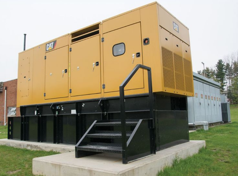
A generator that starts is not the same as a generator that’s ready. In South Africa, where power interruptions are part of normal operations planning, facilities can’t afford “it ran last month” confidence. A standby set must take load cleanly, hold voltage and frequency under stress, switch safely through the ATS, and run long enough to prove cooling, fuel delivery and control stability. That’s what diesel generator load bank testing is for. It turns assumptions into evidence.

This article explains why load bank testing matters, how ATS maintenance protects safe changeover, and what a practical commissioning checklist should include for facilities managers running hospitals, retail sites, logistics DCs and multi-site portfolios.

Why “Starts” Don’t Equal “Ready”

A light no-load run tells you very little. Most generator issues show up when the set is forced to do real work, including:

  • Wet stacking: running too lightly can leave unburnt fuel and soot in the exhaust, reducing efficiency and creating future faults.
  • Overheating under load: marginal cooling systems often look fine at idle, then fail when heat rises.
  • Voltage and frequency instability: regulators and governors can drift and only reveal problems under step loads.
  • Fuel supply restrictions: blocked filters and weak lift pumps might cope at low demand, then starve at higher load.
  • Protection trips: low oil pressure, high coolant temperature, or sensor issues often trigger only during sustained operation.
  • Switching failures: an ATS that is dirty, worn, or misconfigured can fail the changeover even if the generator itself is perfect.

In short: a standby set that “starts” is a partial test. A standby set that “takes load” and stays stable is the one you can rely on.

The risk of untested standby power

When backup power fails, the consequences are rarely limited to inconvenience. For facilities, it can mean:

  • lost cold chain and spoilage
  • downtime and SLA penalties
  • damaged IT equipment from unstable power transfer
  • health and safety issues (especially healthcare and high-occupancy sites)
  • reputational damage and compliance exposure

This is why testing must be planned and documented. If you’re accountable for uptime, you need proof.

Load bank theory: what you’re actually testing

A load bank is a controlled electrical load that “forces” the generator to work at specific percentages of its rated capacity. This proves performance under realistic conditions without relying on your building load to be present or predictable.

A proper test validates:

  • Voltage regulation: stability and acceptable deviation under load
  • Frequency control: the ability to hold frequency as load steps change
  • Temperature management: cooling system integrity under sustained heat
  • Fuel delivery: filtration, lift pump, injectors, and fuel quality resilience
  • Exhaust condition: evidence of wet stacking or poor combustion
  • Control and alarms: sensors and safety systems behave correctly when stressed

It’s also a good opportunity to trend the unit over time, so you can spot decline before it becomes failure.

Step-by-step: diesel generator load bank testing (a practical approach)

A useful test isn’t about “how long can it run”. It’s about a repeatable procedure and documented outcomes.

1) Pre-test checks (before you apply load)

  • Verify oil level and condition (and check for fuel dilution smell)
  • Check coolant level and visible leaks
  • Inspect belts, hoses, clamps and radiator cleanliness
  • Confirm battery health, terminals and charging voltage
  • Confirm fuel level and check for water contamination
  • Verify earth connections and cable integrity
  • Confirm control panel alarms are functional and date/time are correct
  • Confirm ATS is in correct mode and site safety measures are in place

2) Warm-up and baseline readings

Start the generator and allow warm-up. Record:

  • voltage and frequency at no-load
  • oil pressure
  • coolant temperature
  • battery charging rate
  • exhaust smoke behaviour

3) Load steps and stability checks

Apply load in stages, for example:

  • 25% load
  • 50% load
  • 75% load
  • 100% load (if safe and required by your compliance plan)

At each stage, allow stabilisation and record:

  • voltage and frequency stability
  • temperature rise and control response
  • engine sound and smoke behaviour
  • any alarm events or irregularities

4) Sustained run and heat-soak

The value of load bank testing is the sustained run. A shorter “tick-box” test can miss:

  • slow coolant rise
  • marginal fan performance
  • fuel starvation at sustained demand
  • thermal shutdown conditions

5) Controlled unload and cool-down

Remove load in stages and allow cool-down before shutdown. This protects the engine and turbo components and prevents false post-test issues.

Pass/Fail Criteria That Stand Up to Audits

Facilities often ask: “What counts as a pass?” The answer should be defined before testing, not guessed afterwards. A credible test uses thresholds that can be explained, repeated, and presented during audits.

A robust pass/fail framework includes:

  • Start and accept load within target time (as defined by your facility requirement)
  • Stable voltage and frequency under each load step
  • No nuisance trips or critical alarms during sustained load
  • Cooling system holds within safe operating range
  • No excessive smoke or evidence of wet stacking under meaningful load
  • ATS changeover operates correctly without arcing, sticking, or abnormal heat
  • Post-test inspections show no leaks, abnormal smells, or loose connections

If any section fails, the test is still valuable, because it tells you exactly what to fix before the next outage.

ATS maintenance: the part people forget until it fails

Even a perfect generator is useless if the ATS doesn’t transfer power reliably. ATS maintenance matters because it’s a mechanical switching device operating under high current. Contact wear and contamination can cause:

  • delayed transfer
  • partial contact and overheating
  • failure to switch back
  • nuisance alarms
  • arcing that damages the switch

What ATS maintenance should include

  • Visual inspection for discoloration, soot, or heat damage
  • Contact inspection and cleaning (where design allows)
  • Torque checks on cable lugs and terminations
  • Verification of control wiring and sensing lines
  • Functional tests of transfer and re-transfer
  • Verification of timers, delays, and settings to match site requirements
  • Infrared scan (where available) to identify hot spots under load

For multi-site operations, standardising ATS service routines is one of the easiest ways to reduce risk.

Fuel, cooling and exhaust checks that prevent failures

Fuel system basics (often the real culprit)

  • Replace filters to interval, not when the generator struggles
  • Drain water separators and check for microbial growth
  • Verify tank breathers and fuel pickup integrity
  • Ensure fuel quality management is in place for standby tanks (fuel “goes stale”)

Cooling system basics (why marginal sets fail under load)

  • Clean radiators and cooling packs properly (dust build-up is common)
  • Pressure test caps and check hose integrity
  • Verify fan belt tension and fan clutch behaviour (if applicable)
  • Confirm coolant concentration and inhibitor health

Exhaust and wet stacking indicators

Light-load “exercise runs” can create soot build-up and unburnt fuel residue. Load bank testing is one of the best ways to clear wet stacking and confirm healthy combustion under real demand.

Reporting and compliance evidence

A professional test produces evidence you can file, trend, and present. The report should include:

  • test date, site, unit details and rated capacity
  • load stages and duration at each stage
  • voltage/frequency readings and stability notes
  • oil pressure and temperature trends
  • alarm events and corrective recommendations
  • ATS test results and observations
  • clear pass/fail summary and next actions

This turns generator maintenance into a managed risk programme, not reactive firefighting.

AMCS service options for standby power

AMCS can support facilities with:

  • planned diesel generator load bank testing programmes
  • ATS maintenance and changeover verification
  • commissioning checklists for new installs or relocated sets
  • remedial repairs based on test outcomes
  • multi-site scheduling and standardised reporting for portfolio management

Whether you run one site or twenty, the goal is the same: predictable readiness you can prove.

Conclusion: readiness is proven, not assumed

Standby power is insurance. But like any insurance, it only works if it’s real. Diesel generator load bank testing proves your generator can do what it’s meant to do, and ATS maintenance ensures the power actually gets to your building safely and reliably.Ready to replace assumptions with evidence?
Enquire today about diesel generator load bank testing, ATS maintenance, and commissioning checklists with AMCS.

Choosing the Right Heavy-Truck Clutch Kit: Parts Quality, Fitment and AMT Calibration

Choosing the Right Heavy-Truck Clutch Kit

Clutches don’t usually fail “all at once”. They slip a little under load, they start smelling hot on hills, engagement becomes inconsistent, and drivers compensate by riding the pedal or forcing shifts. In long-haul operations, that becomes downtime. In urban distribution, it becomes repeated comebacks and accelerated wear. The right heavy truck clutch kits, fitted correctly and followed by proper AMT clutch calibration where applicable, protect driveline components and keep shift quality consistent.

This article explains what’s inside a clutch kit, how to spot root causes instead of symptoms, and why installation and calibration are just as important as the parts you choose.

Symptoms vs Root Causes in Clutch Failures

Clutch complaints often sound the same:

  • slipping under load
  • judder on take-off
  • hard gear engagement
  • clutch drag (gears grind or vehicle creeps)
  • burning smell after pulls
  • inconsistent bite point

But the root cause isn’t always “worn clutch plate”. Common underlying causes include:

  • oil contamination from rear main seal or input shaft seal leaks
  • warped flywheel surface or incorrect machining
  • release bearing or fork wear causing incomplete release
  • pilot bearing issues creating misalignment
  • incorrect clutch adjustment or air/hydraulic assist problems
  • driver technique and duty cycle mismatch
  • on AMT systems: missed calibration and adaptation reset after installation

If you replace the clutch without addressing these, you’ll shorten the life of the new kit.

What a heavy truck clutch kit should include

Most quality clutch kits include:

  • friction plate (driven plate)
  • pressure plate
  • release bearing
  • alignment tool (sometimes)

Depending on the application, you may also need:

  • pilot bearing
  • release fork, pivot, or wear bushes
  • hydraulic master/slave components
  • flywheel bolts or pressure plate bolts
  • clutch brake (where applicable on certain drivetrains)

A kit can be “complete” and still be the wrong choice if it isn’t matched to vehicle duty cycle and torque requirements.

Parts quality: what to look for before you buy

Friction material and heat behaviour

Different friction compounds handle heat differently. For heavy vehicles:

  • high heat tolerance reduces glazing and slip under long pulls
  • stable friction coefficient improves predictable engagement
  • durability matters more than “soft” feel if the vehicle is always loaded

Pressure plate clamping force

Too little clamping force leads to slip. Too much can increase pedal effort or stress components. The correct kit balances:

  • torque capacity
  • drivability
  • long-term wear characteristics

Release bearing quality

A release bearing failure can take out a new clutch. Signs of poor bearing quality include:

  • noisy operation early in the clutch’s life
  • rough feel through pedal or linkage
  • premature failure under heat

For fleets, bearing quality is often the difference between a long-life job and a repeat job.

Fitment essentials that protect the kit and the warranty

Good parts can fail quickly if the fitment is wrong. Proper installation includes:

  • Flywheel inspection and preparation
    Check for heat cracks, hotspots, runout, and surface damage. If machining is required, it must be correct and consistent.
  • Correct bolt torques and tightening sequence
    Pressure plates must be tightened evenly to avoid distortion.
  • Alignment and pilot bearing checks
    Misalignment causes vibration, uneven wear and release issues.
  • Seal checks (before installing the new clutch)
    If oil contamination caused the failure, seals must be replaced before the new kit goes in.
  • Release mechanism inspection
    Fork, pivot points, bushings and linkage must move freely and return correctly.

This is also where workshop discipline matters: cleanliness, correct tools, and avoiding shortcuts.

AMT clutch calibration: the step that prevents comebacks

Automated Manual Transmissions (AMTs) rely on learned values and precise actuator movement. After clutch replacement, the system often requires:

  • clutch bite point calibration
  • actuator end-stop learning
  • wear adaptation reset (where applicable)
  • gearbox shift quality verification
  • fault scan and clear, then re-scan after road test

Calibration steps that protect warranty and shift quality

A solid AMT workflow looks like this:

  1. Confirm correct clutch kit and mechanical fitment.
  2. Scan for existing gearbox/clutch actuator faults.
  3. Perform required adaptation reset and bite point calibration using correct tools.
  4. Run actuator tests and confirm smooth movement.
  5. Conduct a controlled road test through operating ranges and loads.
  6. Re-scan the system and confirm no new faults or abnormal parameters.
  7. Document the calibration results for warranty and fleet records.

Skipping calibration can cause harsh shifts, early wear and repeat breakdowns that look like “bad parts” but are actually missing procedure.

Bedding-in and driver practice (what fleets get wrong)

A new clutch needs controlled bedding-in, especially in heavy duty applications. Common mistakes include:

  • immediate heavy towing without bedding-in
  • excessive slipping on inclines
  • resting foot on the pedal
  • riding the clutch in stop-start conditions

Work with drivers on:

  • avoiding unnecessary slip
  • using correct gear selection early
  • minimising clutch heat build-up
  • reporting early signs (smell, bite change, judder)

AMCS supply and install: what you should expect

AMCS supports clutch replacement through:

  • correct heavy truck clutch kit selection based on duty cycle
  • professional installation with component checks that protect the new kit
  • inspection and correction of root causes (seals, flywheel, release system)
  • AMT clutch calibration and post-install validation
  • documentation for fleet records and warranty protection

Conclusion: the right clutch job is a system job

If you only replace the clutch plate, you’re gambling. A clutch job that lasts considers the kit quality, the flywheel and seals, the release system, and the calibration workflow on AMTs. When those steps are done properly, shift quality improves, driveline stress drops, and downtime becomes far less frequent.

Need a clutch kit that lasts, fitted and calibrated correctly?
Enquire today about heavy truck clutch kits, professional clutch replacement and AMT clutch calibration with AMCS.

Air Systems That Don’t Fail: Air Dryer Service & Governor Testing for Heavy Trucks

Air Dryer Service & Governor Testing for Heavy Trucks

Air brakes are only as good as the air feeding them. If moisture and oil mist are getting past the dryer, or the governor is allowing unstable pressure cycles, the damage spreads quietly through the system. Valves start sticking, relay exhausts hiss, brake response becomes inconsistent, and suddenly you’re replacing components that should have lasted far longer. In South Africa’s mix of long-haul heat, dusty sites, and stop-start distribution routes, air quality and pressure control are not “nice to have”. They are the backbone of safe stopping and predictable uptime.

This guide breaks down how air dryers and governors actually work, how moisture ruins air brakes, and how to test, service, and document the system properly. It’s written for fleet managers and workshop heads who want fewer surprises and more repeatable brake performance.

Why Moisture Ruins Air Brakes

Compressed air naturally carries water vapour. When that air cools in reservoirs and lines, water condenses into liquid. If your dryer isn’t doing its job, that water spreads into valves, modulators, and brake chambers.

Moisture causes problems in three main ways:

  • Corrosion inside valves and relay bodies: Rust and pitting lead to leaking seats, sluggish response, and “mystery” pressure loss.
  • Contamination and sticky operation: Water combines with oil carryover and dust to create sludge that blocks ports and prevents proper exhaust or application.
  • Freezing risk in cold conditions: While most of South Africa isn’t freezing, high-altitude routes and winter mornings can still create icing issues that lock valves and restrict airflow.

The end result isn’t always a dramatic failure. It’s often a slow decline: more compressor cycling, more small leaks, uneven brake timing, and higher wear rates across the fleet.

The hidden cost: valve contamination

When a dryer allows wet air through, you start seeing repeat issues like:

  • relay valves that won’t seal properly
  • quick-release valves that “spit” or stick
  • trailer supply and service faults that keep returning
  • ABS/EBS air modulators suffering premature wear

Fixing the symptoms without fixing the air quality just guarantees the problem comes back.

Air dryer fundamentals in plain language

Air dryers don’t “create” dry air. They remove moisture from compressed air before it reaches the reservoirs, using a desiccant cartridge and a purge cycle.

A typical heavy-truck air dryer includes:

  • Desiccant cartridge: a drying medium that absorbs moisture.
  • Oil coalescing stage (on many systems): reduces oil mist that would otherwise destroy the desiccant.
  • Purge valve: dumps collected moisture and contaminants during purge.
  • Check valve: prevents backflow during purge.
  • Heater (common on many trucks): prevents icing and helps purge effectiveness.

If the purge cycle is weak, the cartridge saturates early. If oil carryover is high, the cartridge becomes contaminated. If the purge valve is leaking, the system loses pressure and the compressor runs constantly.

Governor bands and why they matter

The governor controls compressor behaviour. It switches the compressor between loading (building pressure) and unloading (stopping pressure build) at set points.

Two numbers define it:

  • Cut-in pressure: when the compressor starts building air again.
  • Cut-out pressure: when the compressor stops building because pressure is high enough.

If cut-out is too low, you’ll never have stable reserve pressure. If cut-in is too high, the system drops too far before recovering, which can affect brake response and accessory systems. If the governor is “hunting” (rapid cycling), it increases wear, overheating, and moisture carryover because the dryer doesn’t get a proper purge pattern.

Step-by-step tests that should be standard in every fleet

A proper air system check doesn’t need guesswork. It needs a repeatable method and basic measurements logged over time.

1) Build-up time test (compressor health indicator)

With the engine running, time how long it takes to build from a lower pressure to normal operating pressure. Slow build-up can indicate:

  • compressor wear
  • restrictions
  • dryer blockage
  • major leaks
  • governor issues

Build-up time alone doesn’t diagnose everything, but it’s a strong early warning trend across a fleet.

2) Cut-in / cut-out testing and purge verification made practical

This is one of the most useful tests because it checks both the governor and the dryer purge behaviour.

How to do it:

  1. Fully charge the system until the compressor unloads.
  2. Note the cut-out pressure on the gauge.
  3. Fan the brakes to drop pressure gradually.
  4. Note the cut-in pressure when the compressor starts building again.
  5. Listen and observe the dryer purge at cut-out.

What you’re looking for:

  • cut-in and cut-out are stable and repeatable
  • purge is strong and consistent
  • no constant hissing from the purge valve after the purge event
  • no rapid cycling between cut-in and cut-out

If you don’t hear a purge, or it’s weak and wet, you’re likely storing moisture in the system.

3) Static and applied leakage tests (the leak “truth test”)

Micro-leaks often hide under normal operation. A structured test finds them.

  • Static leak test: engine off, full pressure, brakes released. Record pressure loss over a set period.
  • Applied leak test: same test but with brakes applied. This often exposes chamber and circuit leaks.

When combined with purge checks, these tests tell you whether you’re dealing with:

  • poor air quality (wet system)
  • valve contamination
  • worn chambers or fittings
  • compressor or governor control issues

4) Reservoir drain inspection (quick evidence)

Draining reservoirs tells you what your system is collecting:

  • clear water indicates moisture saturation
  • milky fluid can suggest oil contamination
  • rust particles indicate corrosion
  • excessive moisture indicates dryer failure or purge problems

Reservoir drains don’t replace proper testing, but they are a fast, practical indicator.

Cartridge service and why timing matters

Air dryer cartridges don’t last forever. They lose effectiveness based on:

  • mileage and duty cycle
  • humidity and temperature
  • compressor oil carryover
  • purge quality
  • dust exposure

A common mistake is replacing a cartridge only after failures start. By then, wet air has already moved through valves and reservoirs. Preventative replacement protects the whole system.

Practical best practice for fleets

  • Standardise cartridge change intervals across the fleet based on duty cycle (line-haul vs urban).
  • Pair cartridge replacement with purge valve inspection.
  • If oil carryover is suspected, address compressor condition or add proper filtration where applicable.
  • Log each service with date, vehicle ID, cut-in/cut-out pressures, and any abnormal findings.

Leak tracing that goes beyond “spray and pray”

Soap solution is useful, but systematic isolation is faster:

  • Start at the dryer and purge valve: constant hiss here is common.
  • Move to reservoir fittings and drain valves.
  • Check relay valves and exhaust ports.
  • Check brake chambers, especially spring brake chambers.
  • For trailers, check coupling seals and trailer supply circuits.

If the system is wet, you’ll often find multiple “small” leaks because valve seats have been damaged. Fixing one leak won’t stop the pressure loss.

AMCS on-site vs workshop: what makes sense when

A lot of air system work can be done at your depot to reduce downtime:

  • cut-in/cut-out testing
  • purge verification
  • leakage testing
  • reservoir drains and moisture checks
  • initial leak tracing
  • basic component swaps where access allows

Workshop work is best for:

  • deep valve contamination issues
  • compressor inspections/repairs
  • dryer housing or heater faults
  • multiple system repairs that need controlled conditions
  • full system reconditioning where wet air has caused widespread problems

The key is that on-site testing and reporting should feed a proper maintenance plan, not a once-off fix.

Records, compliance and fleet consistency

For fleets, one of the biggest wins is consistency. When every unit is tested the same way and results are logged, you can:

  • spot a failing compressor before it fails completely
  • catch a weak purge cycle early
  • compare build-up times and leakage rates across vehicles
  • prove brake system upkeep during audits and incident investigations

A simple record template should include:

  • cut-in pressure
  • cut-out pressure
  • build-up time
  • static leak loss
  • applied leak loss
  • reservoir drain findings
  • actions taken and parts replaced

Conclusion: dry air is cheaper than repairs

Air systems don’t usually fail dramatically without warning. They degrade. Moisture and oil contamination shorten the life of every downstream component, and pressure instability shows up as brake inconsistency, excessive compressor cycling, and higher service costs.

If your fleet is chasing repeat valve issues, recurring leaks, or inconsistent brake feel, don’t start by replacing parts again. Start at the source: air dryer service and air brake governor testing.Ready to reduce leaks, protect valves, and stabilise brake performance?
Enquire today about air dryer service, pressure control testing, and fleet-wide air system maintenance programmes with AMCS.

Inside AMCS’s Advanced Diagnostics Suite: ECU, ABS and Legal ODO Correction Workflows

ECU, ABS and Legal ODO Correction Workflows

If your workshop is still diagnosing modern trucks by “best guess”, you’re paying for it in downtime and unnecessary parts. Today’s fleets run on data: ECUs, modules, sensors, networks, and interlinked systems that can trigger faults far away from the real root cause. A single ABS wheel-speed signal problem can look like a braking issue, a gearbox complaint, or even a drivability fault depending on the vehicle’s logic.

The difference between expensive guessing and reliable repair is a structured diagnostic workflow. In this article, we’ll unpack what AMCS means by advanced truck diagnostics, what ECU and ABS diagnostics should look like in practice, and how legal ODO correction fits into a compliant, documented process.

Why Guided Diagnostics Beats Guesswork

Guesswork feels fast, but it’s usually slow. It leads to:

  • parts swapped “to see if it fixes it”
  • repeat comebacks because the cause wasn’t addressed
  • downtime that drags on while the fault returns intermittently
  • damage caused by incorrect assumptions (especially in braking and driveline systems)

Guided diagnostics flips the process. Instead of starting with the loudest symptom, you start with evidence and follow a repeatable decision tree.

A proper diagnostic approach should always answer:

  • What is the fault code actually describing?
  • What conditions trigger it?
  • What data supports the fault?
  • What tests confirm the cause?
  • What repair removes the cause permanently?

Tooling overview: what “advanced” means in the real world

Advanced diagnostics is not just plugging in a scanner. It typically involves:

  • reading manufacturer-specific codes, not generic ones
  • live parameter monitoring and recording
  • actuator tests (commanding outputs to verify response)
  • network checks (CAN / J1939 integrity and communications)
  • guided test plans that validate sensors, wiring, and modules in a logical order
  • producing a report that can be used for maintenance planning and compliance

It’s also about being able to interpret results correctly, not just retrieve them.

ECU diagnostics: not just codes, but context

The ECU (engine control unit) is constantly comparing expected values to actual values. It uses fuel pressure, boost pressure, airflow, temperatures, and more to decide whether the engine is operating within safe limits.

What ECU diagnostics should include

  • Fault codes with freeze-frame data (what the engine was doing at the moment the fault logged)
  • Live data analysis (is the sensor believable under real operating conditions?)
  • Comparison tests (does the signal track correctly against a known reference?)
  • Actuation tests (can the system physically respond when commanded?)

Common examples where context matters

  • A boost code doesn’t automatically mean a turbo failure. It could be a charge-air leak, actuator issue, wiring fault, or a sensor reporting incorrectly.
  • A fuel pressure deviation might be a supply restriction, a failing sensor, poor electrical feed, or actual mechanical wear.
  • A temperature fault could come from a wiring issue, not an overheating event.

From live data to root cause: a structured test plan

A structured test plan prevents wild guesses. A typical approach looks like this:

  1. Confirm the complaint and reproduce it under controlled conditions.
  2. Scan and capture codes and freeze-frame data.
  3. Monitor live data while recreating the fault.
  4. Run actuator tests to confirm component response.
  5. Verify wiring integrity (voltage drop, continuity, connector checks).
  6. Confirm mechanical condition only after electronic verification.
  7. Repair, clear codes, and validate with a repeat test.
  8. Export a report with findings and recommendations.

That workflow is what reduces downtime and prevents repeat failures.

ABS diagnostics: where safety and uptime meet

ABS and EBS systems rely on accurate wheel-speed data, clean signals, stable power, and correct modulation behaviour. A fault in any of these can cause:

  • warning lamps
  • reduced braking confidence
  • stability control limitations
  • compliance concerns in audits and inspections

What proper ABS diagnostics looks like

  • Wheel-speed sensor signal tests (not just “replace sensor”)
  • Tone ring inspection (damage, dirt build-up, misalignment)
  • Sensor air gap checks and correct seating
  • Harness checks (chafing and intermittent opens are common)
  • Modulator and valve tests where supported
  • System communication checks if the fault suggests network issues

Why ABS faults are often intermittent

Many ABS complaints happen “only sometimes”, especially:

  • after wash bays and wet weather
  • on rough roads where wiring moves
  • when trailer connections are inconsistent
  • when sensor air gaps change as bearings wear

A good diagnostic process catches the intermittent nature by logging live data and checking the physical condition of the system.

Legal ODO correction: when it’s needed and how it’s handled

Odometer (ODO) correction is a sensitive topic and must be handled legally and transparently. There are legitimate cases where correction is required, for example:

  • instrument cluster replacement
  • ECU/module replacement that affects recorded mileage
  • documented software issues that corrupt the displayed value
  • repair scenarios where recorded mileage must reflect accurate data history

What matters is compliance and documentation. Any legal ODO correction process should include:

  • verified reason for correction
  • recorded before/after values
  • supporting documents (repair invoices, module serial numbers)
  • written confirmation for the customer file
  • adherence to applicable regulations and ethical standards

AMCS approaches this as a documented workflow, not a “quick fix”. If the paperwork and justification aren’t clear, it shouldn’t be done.

Case-style examples: what advanced diagnostics prevents

Example 1: “Turbo problem” that wasn’t a turbo

Symptoms: poor pull, occasional limp mode, boost-related fault code.
Root cause: charge-air hose leak under load and a sensor signal reading incorrectly due to connector damage.
Outcome: hose repair + connector fix, turbo saved, downtime reduced.

Example 2: ABS light and uneven braking feel

Symptoms: ABS warning lamp flickers, driver reports inconsistent braking feel.
Root cause: wheel-speed sensor air gap and tone ring contamination, plus harness rub-through starting to fail intermittently.
Outcome: correct seating, cleaning, harness repair, verified through live data.

Example 3: Cluster replacement and mileage integrity

Issue: cluster replacement caused incorrect displayed mileage.
Approach: documented correction with before/after records, customer file updated, compliance protected.

What AMCS delivers after diagnostics

A professional diagnostic outcome should leave you with more than “fault cleared”. It should leave you with:

  • a clear explanation of the root cause
  • the tests used to confirm it
  • what was repaired or replaced
  • what should be monitored going forward
  • service recommendations to prevent a repeat
  • documentation that supports fleet planning and compliance

Conclusion: the best repair starts with proof

Advanced diagnostics is not about fancy tools. It’s about lowering downtime by following evidence, validating signals, and confirming mechanical reality only after electronic truth is established. When fleets adopt structured ECU and ABS diagnostics, they reduce repeat repairs, protect safety-critical systems, and stop wasting money on parts that were never the problem.Want faster fault-finding with clearer answers?
Enquire today about advanced truck diagnostics, including ECU diagnostics, ABS diagnostics, and compliant legal ODO correction workflows with AMCS.

Cooling & Charge-Air Systems: Radiators, Intercoolers, Viscous Fans and CAC Leak Testing

Cooling & Charge-Air Systems

Engines lose power and longevity when cooling and charge-air systems are ignored. A small boost leak can rob torque and raise exhaust temperatures. A lazy viscous fan can let coolant spike at the worst moment. Over time, heat and contamination shorten component life and fuel economy. This article shows how AMCS diagnoses and restores cooling systems and charge-air circuits so your fleet runs cooler, stronger and for longer.

Why Temperature Control Is a Profit Lever

Consistent coolant and intake-air temperatures protect head gaskets, turbochargers, EGR coolers and aftertreatment. They also stabilise fuel burn. Every degree of unnecessary heat costs money in lost efficiency and early component replacement. On long grades, towing, or stop-start routes, the difference between a clean, sealed system and a marginal one is the difference between uptime and a roadside stop.

Cooling System Foundations

  • Radiator & Shroud: Heat exchanger efficiency depends on unobstructed fins, straight tubes and proper shroud alignment.
  • Thermostat & Water Pump: Control flow and warm-up rate; a weak pump or sticky stat causes oscillating temperatures.
  • Hoses, Clamps & Caps: Seals keep the system pressurised; small seeps reduce the boiling point and invite air.
  • Viscous Fan & Clutch: Locks up when hot air exits the radiator, pulling high airflow; worn clutches slip and overheat the bay.

Failure Signs You’ll Notice

  • Gradual temperature creep under load followed by sudden spikes
  • Coolant loss without obvious puddles; stained fins and hose ends tell the story
  • High intake-air temps (IAT) with normal coolant temp, pointing to intercooler issues
  • Over-speeding fan noise that never fully engages or a fan that rarely ramps up at all

Charge-Air (Intercooler) Health: Boost In, Power Out

A sealed CAC keeps intake density high and EGTs low. Even modest leaks force the turbo to work harder for less result.

CAC Leak Testing (AMCS Method)

  1. Visual Check: Oil mist trails, split hoses, loose clamps, chafed elbows.
  2. Pressure Test: Cap the system, pressurise to a safe specified value, and monitor decay.
  3. Smoke Test: Pinpoint pinholes at crimps, end tanks and welds.
  4. Data Capture: Compare commanded vs achieved boost and IAT during a controlled pull.

Note: Persistent soot load in the DPF often traces back to weak CAC sealing or high IAT, not just fueling.

Viscous Fans and Shrouds: The Unsung Heroes

  • Engagement Check: With a scan-tool or temp probe, verify fan-on thresholds and ramp behaviour.
  • Clutch Health: Look for silicone fluid leaks, play and roughness.
  • Shroud Geometry: Missing shroud sections reduce draw; ensure fan tip clearance is correct.
  • Electrical Controls: On electronically-controlled clutches, confirm signal and relay integrity.

Radiators, Thermostats and Pumps: Precision Over Parts Swaps

  • Radiator Service: Chemical flush where appropriate, fin straightening, pressure testing and cap replacement.
  • Thermostats: Test open temps in a controlled bath; confirm full stroke; replace with OEM-spec units.
  • Pumps: Check bearing noise and shaft play; confirm impeller integrity (plastic impellers can erode).
  • Coolant Chemistry: Use the correct inhibitor package; mix with demineralised water and maintain concentration.

Data-Driven Validation on the Road

After repairs, AMCS performs a structured road test:

  • Baseline & Pulls: Steady-state cruise and grade climbs to collect coolant, IAT and boost traces.
  • Fan Behaviour: Verify engagement under repeatable conditions.
  • Heat-Soak Recovery: Stop-start segment to confirm temperature recovery and idle stability.
  • Reporting: You receive comparative plots and service recommendations.

Preventative Intervals That Prevent Spikes

  • Every Service: Pressure-cap test, hose inspection, coolant level and mix check, debris removal from radiator/intercooler faces.
  • Quarterly: CAC smoke test if routes include dusty sites or gravel roads; shroud and fan clutch inspection.
  • Semi-Annual: Coolant test strip, thermostat verification, radiator pressure test and boost-leak data review.
  • After Any Overheat Event: Full system inspection and oil analysis to check for collateral damage.

Driver and Depot Practices That Help

  • Don’t power-wash fins head-on; wash gently from the engine side out where possible.
  • Inspect clamps after every major service; retighten to spec.
  • Keep spares of the most failure-prone elbows and clamps used across your fleet.
  • Audit coolant storage and mixing; label drums and jugs to avoid contamination.

How AMCS Restores Cooling and Charge-Air Performance

  • On-site inspections: CAC smoke tests, clamp and hose checks, radiator face cleaning and coolant top-ups.
  • Workshop diagnostics: Pressure tests, fan clutch replacements, radiator repairs and thermostat/pump changes.
  • Proof of improvement: Before/after temperature and boost plots, with notes on thresholds and engagement points.
  • Fleet standardisation: We recommend common hose types, clamp sizes and coolant specs to simplify spares and reduce errors.

Ready to cut heat, protect engines and recover lost power?

Enquire today about cooling system maintenance, charge-air leak testing and fleet heat-management programmes.

Air Brake & EBS Maintenance: Leak Testing, Slack Adjusters, and Brake Balance for Heavy Trucks

Air Brake & EBS Maintenance

Modern heavy trucks rely on air brakes working in step with EBS to deliver consistent, predictable stopping power. When leaks creep in, slack adjusters drift, or EBS sensors go out of range, wheels no longer share the load equally. That shows up as longer stopping distances, hot hubs, rapid lining wear and compliance headaches. This practical guide explains how the system works, what fails, and how AMCS maintains brake performance across single units and full combinations.

Why Air Brake Health Determines Fleet Safety

Air brakes convert stored compressor energy into precise clamping force at each wheel. The system must retain pressure, respond quickly, and apply force evenly from axle to axle. EBS adds electronic control to modulate pressure and coordinate truck and trailer braking in milliseconds. Any weakness in supply, timing or balance sacrifices stopping consistency and heats components unnecessarily.

Typical South African Failure Patterns

  • Chronic micro-leaks that never trip alarms but keep compressors cycling and dryers saturated
  • Slack adjusters that haven’t been verified since shoe changes, causing side-to-side imbalance
  • Water-logged air from neglected dryers, corroding valves and relay bodies
  • Wheel-speed sensor gaps and dirty tone rings that upset EBS stability logic
  • Trailer wiring and earth faults that cause intermittent EBS communication drops

System Overview: From Compressor to Shoes

  • Compressor & Governor: Builds system pressure and controls cut-in/cut-out.
  • Air Dryer: Removes moisture and oil mist; a tired cartridge lets water into valves.
  • Reservoirs & Check Valves: Provide staged supply and isolation.
  • Foot/Brake Valve & Relays: Translate driver demand into wheel-end pressure quickly.
  • Slack Adjusters & Foundation Brakes: Convert push-rod movement into shoe force.
  • EBS Hardware: ECU, modulators, pressure sensors, wheel-speed sensors and ABS rings coordinate the whole system.

Step-by-Step Leak Testing That Catches the Small Stuff

  1. Stabilise Pressure: Engine off, full system charged.
  2. Static Test: Record pressure loss over 2 minutes at rest.
  3. Applied Test: Hold service brake; measure loss with and without trailer connected.
  4. Bubble & Tone Tests: Soapy solution on unions, chambers, relay vents; listen for valve seat hiss.
  5. Circuit Isolation: Close tank drains and isolate circuits to pinpoint the offender.
  6. Compressor Health: Verify cut-in/cut-out, build time, and dryer purge cycle.

Pro tip: A small constant loss at a relay exhaust can be valve contamination from wet air. Dryer service often fixes “mystery” leaks.

Slack Adjusters: Manual vs Automatic, and Why “Set & Forget” Fails

  • Manual Adjusters: Require calibrated adjustment to specified push-rod travel. Over-tightening drags linings; under-tightening lengthens stroke.
  • Automatic Adjusters (ASA): Shouldn’t be manually wound regularly. If they aren’t maintaining stroke, diagnose foundation issues first (worn cams, seized rollers, bent return springs).
  • Verification: With a gauge, measure and record push-rod travel per wheel. Compare left/right on the same axle and across axles to confirm balance.

Correct Setup Procedure (Condensed)

  • Inspect shoes, rollers, pins, return springs; replace in axle sets.
  • Verify cam bushings and anchor pins.
  • Set push-rod free play to spec; apply brakes several times; re-measure.
  • Log final travel and note any wheel that trends toward max stroke between services.

Brake Balance, Timing and Trailer Dynamics

Even application matters as much as absolute force. Balance issues often live in the details:

  • Valve & Relay Location: Long, small-bore lines delay signal; relocate or upsize where practical.
  • Load-Sensing Valves: Confirm settings after suspension work; mis-set valves under-brake loaded axles.
  • Trailer Matching: Check truck and trailer control timings and pressures; standardise components on multi-trailer fleets to avoid “mismatched” responses.
  • Lining Compatibility: Mixed friction materials across axles can change heat profiles and wear rates.

EBS Diagnostics Without the Guesswork

  • Wheel-Speed Sensors: Verify air gaps, ring cleanliness and continuity.
  • Modulators & Pressure Sensors: Run guided tests; compare commanded vs measured pressure.
  • Fault Trees: Address primary faults first; clear and road test; re-scan to catch intermittent issues.
  • Harness Checks: Trailer sockets, earth continuity and pin tension are common culprits in intermittent EBS drops.
  • Performance Validation: Conduct controlled stops and record brake temperatures to confirm balance.

Preventative Service Intervals That Actually Work

  • Every Service: Reservoir drains, dryer purge check, quick leak test, visual hose inspection.
  • Quarterly: Full static/applied leak test, push-rod travel logging, valve function test.
  • Semi-Annual: Dryer cartridge replacement (or sooner for high-moisture routes), governor verification, detailed EBS scan and data export.
  • Post-Lining Replacement: Mandatory slack adjuster verification and EBS stability check.

What You Can Do Between Services

  • Train drivers to report longer pedal travel, persistent compressor cycling, or ABS lamps that flicker over bumps.
  • Standardise foundation brake components across fleets where possible.
  • Keep a single-page brake balance log for each unit and trailer, updated after every check.

How AMCS Keeps Your Trucks Stopping Straight

  • On-site testing: Leak tests, push-rod measurements and valve checks conducted at your depot to minimise downtime.
  • Workshop repairs: Dryer overhauls, valve replacements, foundation brake rebuilds and EBS fault resolution with OEM-level diagnostics.
  • Documentation: You receive balance logs, EBS reports and service recommendations aligned to your routes and loads.
  • Compliance & safety focus: We prioritise repeatable stopping performance and traceable records for audits.

Ready to improve stop consistency and reduce hot-hub failures?

Enquire today about air brake maintenance, EBS diagnostics and fleet-wide brake performance audits.